Flash Drives have been around for years. They are the little handy devices we all take for granted to store our personal information or work projects on and occasionally misplace. However, not many people know exactly how they work and, more specifically, the complex nature that allows USB flash drives to store thousands of files worth of information all on a device the size of a finger.
Below is a diagram of an average USB drive with its protective shell taken off. What you see are the inner circuits and chips that make a USB drive all possible.
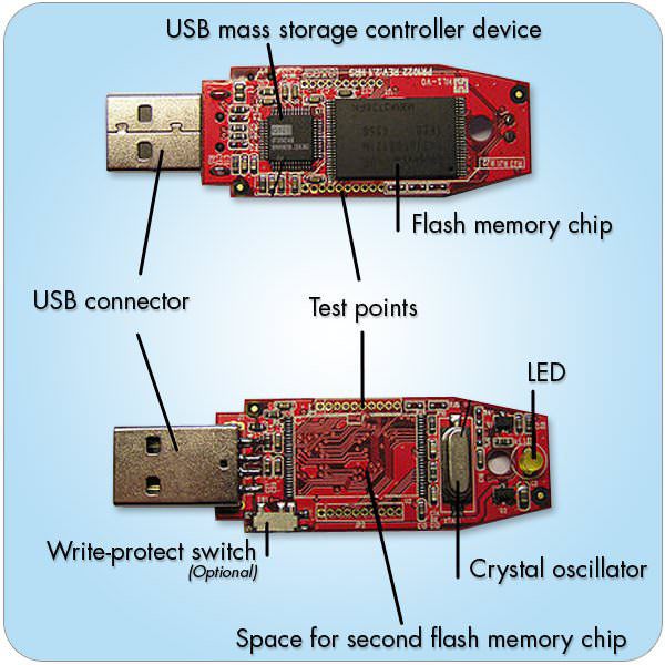
USB Connector – This part of the USB flash drive needs no introduction; it’s the part that physically attaches to a USB hub or port. This part of the device is usually a simple conductive metal, but can sometimes be coated with various other metals including 24k gold to avoid corrosion and provide maximum connectivity.
USB Mass Storage Controller Device – Considered the brain of the USB drive, the controller device is the part of the USB drive that communicates with the host computer or device. It houses a small microcontroller with ROM and RAM that enables the controller to access the flash memory and retrieve the desired information.
Flash Memory Chip – The flash memory is part of the USB drive that actually houses all your information. It’s easily the biggest chip on the USB drive and houses the most information. Typically, when people refer to the data storage capacity, such as 1GB or 16GB, they are referring to this part of the USB drive. As technology has advanced, this chip has been repeatedly upgraded and now the industry standard for USB drives is 1GB, but you can get them as high as 256GB.
This piece is also responsible for the volatility in prices for USB drives in the past couple years. This chip is publicly traded on the Hong Kong stock market and depending on supply vs. demand; the prices can fluctuate dramatically from one week to the next.
Test Points – Test points are used on some USB drives to test the USB during the manufacturing process. This testing looks for flaws as well as makes sure everything is working properly.
Write-Protection Switch – Not all USB drives have the write-protection switch, but for those that do, you have the option of making your USB drive write-protected. When the drive is write-protected, you are unable to put any new information onto the USB, but when the switch is in the off position, it acts just like any other flash drive and allows you to add or delete any piece of information.
LED – The LED light is a indicator that displays when the USB drive is on, as well as when its working. Generally when the USB drive is inserted the light will come on and remain solid, but whenever you are adding, deleting, or accessing files, the LED light flickers to indicate that it is in use.
Crystal Oscillator – The crystal oscillator controls the flow of information within the USB drive using its 12 MHz clock signal. A clock signal is used in all electronic devices and oscillates from one end to another. This signal is similar to a pendulum, rocking back and forth, and is used to help coordinate the actions of all the electronics on the USB drive.
As you can see from the diagram and the descriptions above, USB drives are fairly complicated pieces of technology. Luckily for everyone who uses a USB drive, they’re nowhere near as complicated to use as they are to look at. USB drives come in many different shapes, sizes, capacities, and colors. You can even get custom USB drives made for promotional campaigns, company events, or industry conventions. If you would like to learn more about promotional USB or how customizing a USB drive can help your next promotional campaign, contact Premium USB today!