USB Explained
You may have a general idea of what a USB specification is in the simplest terms—the fact that it is the interface that lets a host computer and peripheral device communicate—but few consumers actually understand much about the technical background of how it works.
AllUSB attempts to help you understand the specification in order to not only broaden your knowledge of USB functions but help you optimize your device applications.
In the early days of USB, the USB 1.1 standard had low and full speed modes, 1.5 Mbits per second and 12 Mbits per second respectively. USB 2.0 introduced high speed at 480 Mbits per second and a slow but gradual adaptation of USB 3.0 SuperSpeed has nearly 5 Gbits per second data transfer rates. We will mainly focus on USB 2.0, as much of the same principles will apply to USB 3.0 with a few exceptions, which will be noted.
The USB is a serial bus that will plug and play peripheral devices. The host computer is in charge of all communications. The computer will detect the type of device that it's hosting, and subsequently loads a compatible driver so that the peripheral can be used. Differential NRZI (non-return to zero, inverted) data passes through the devices in either Isochronous or Asynchronous fashion. Devices use the act of upstreaming and host computers use downstreaming to transmit data between one another.
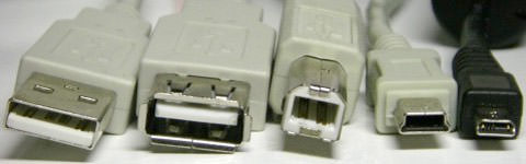
The primary USB connectors are Type A and Type B plugs and sockets. Type A plugs are inserted into a Type A socket which can be found on computers or hubs. Similarly, Type B plugs go into Type B sockets that are built into devices. There are also mini and micro versions of Type A and Type B plugs and sockets. These are used for phones and cameras that demand a smaller sized connection. Micro USB plugs and sockets are a universal standard for cell phone chargers.
USB operates in a tiered star topology for devices. The main host controller has the capacity to operate up to 127 devices at once. This can be accomplished by attaching the host to a hub to create six tiers of hubs with devices. Two hubs must be self-powered. Bandwidth may run out before reaching 127 devices, although it is a theoretical possibility to reach such a capacity.
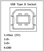
USB cables provide the connection between the device and computer. The cable protects four wires (eight for USB 3.0, which is discussed later). There are D+ and D- wires that are green and white data wires respectively which are twisted together for differential data and single-ended signals. Another wire is the GND wire or ground wire. The last wire is the VBUS, which carries 5V. The connected device may use this as a power supply. USB cables include detachable versions with both A and B plugs as well as a built-in cable connected to the equipment that uses an A plug.
There is not just one way to distribute power from a USB. Devices and hubs will draw their power from an upstream port. Self-powered devices don't even take power from the USB, but from an AC outlet. A bus-powered option will draw approximately 100mA to 500mA from the computer host. If there's no bus activity, the device can power down to 0.5 to 2.5mA. Devices that demand more than 500mA must be self-powered.
A USB transceiver detects connection functions and gives specific standard electrical signaling. It also monitors voltage levels to ensure they are operating properly. The circuit of a transceiver can be found at both ends of data links connecting host and USB device. The upstream transceiver located near the host has two resistors. The downstream transceivers located in devices will spot single-ended signals. Subsequently, the host measures the needed speed by seeing which line pulls 3.3V from the VBUS.
The line states of USB will operate in one of three ways at any one time. A detached state means that a device is unplugged while an attached device means that it is connected to the host. An idle state means that the data lines are separated between low and high states of power.
There are also different device states that can occur. An attached state means that a plugged in device has been discovered on the port. The powered state means that the device is functioning while an addressed state signifies that USB has given the device a 7-bit address. A configured state is when the USB interface is able to communicate with the device. A suspended state implies that the device is powered to a minimum low state.
In terms of USB function and technology, packets are the most basic unit of data transfer. A certain number of bytes are transmitted with each packet. A packet will have an 8-bit SYNC sequence, a 0 to N 8-bit data sequence, an 8-bit packet identifier (PID) and a 2-bit End-of-Packet identifier. Four types of data packets work together in order to accomplish successful data communication and transmission: token packets (IN, OUT, SOF, SETUP), data packets (DATA0, DATA1), handshake packets (ACK, NACK, STALL) and special packets (ERR, PRE, PING, SPLIT).
Token packets are only prompted by the host. An IN token needs a device response, be it NAK, STALL, or DATAX. OUT token comes before the DATAX frame. USB 2.0 devices will get several SOF tokens per millisecond, which mark data transfers.
Handshake packets detail what happens during the data transaction. Handshake packets are limited in returns by transactions that accept flow control. With data packets, each data packet includes a PID, a data field with a specified amount of bytes and a CRC. Data bytes are transmitted in integral amounts. Special packets like PING mark transaction speeds in faster connections.
Frames come into play in that they track time through millisecond increments for the USB host controller. The host controller fills frames with data. A frame will begin with a SOF token packet (the only idle USB packets that also lack a destination). If a device has no activity from USB for a few milliseconds, the device is rendered to a suspended state. A device is generally equipped with a remote function in the descriptor to alert it for activity.
Endpoints are located on USB devices and host controllers which together are equipped with up to 32 endpoints. They are sinks or sources of data that operate in a single direction; 16 transfer data from the host to the device (OUT endpoints) while the other 16 are IN endpoints that carry information from the device to the host computer. The zero endpoint controls bus management in both directions, therefore it will account for two of the connection's endpoints. Configurations must be completed in order to reach an endpoint. This allows for the host to understand what the device is and how to use it. Endpoints are used in four different ways that are known by types of transfers.
Descriptors are a chain of actions responsible for recognizing the host and giving it necessary information about the device. Initially, once the host acknowledges that the device has been plugged in, it resets the USB device to zero to prevent any automatic data downstreaming. Once the descriptor gives the host the proper information about the peripheral, it will load compatible USB drivers to help it operate. Once the driver configures the device it will communicate and respond to data requests.
There are five basic USB descriptors: device descriptors, configuration descriptors, interface descriptors, endpoint descriptors and string descriptors. There is typically only one device descriptor per device. It supplies product information that allows the loading of drivers and it evaluates how many configuration descriptors will be needed.
- Configuration descriptors will measure the amount of power needed. It will determine subsequent descriptors for the interfaces. Only one configuration transpires at a time.
- Interface descriptors will guide the endpoint descriptors in carrying out a specific device command with multiple interfaces working at once. For example, a printer that also scans will use separate interface descriptors for each function.
- Endpoint descriptors will identify details like the data transfer direction, polling and type of transfer while string descriptors give optional yet readable text with three or more fields. If these string descriptors are not implemented, fields will need to be placed at zero.
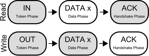
A sequence of three determined packets that transfer data between the host and device is known as a transaction, with four transaction formats to handle data transfers. These formats will vary in how long they take to transfer data and the manner and accuracy in which they do so.
Interrupt transfers use ACK handshake packets. A handshake is a part of a transaction's status stage. Found in peripherals like mice and keyboards, these transfers occur within a very specific transfer time. Interrupt will also keep you informed on any device status changes.
Bulk transfers will also use ACK, but the data transfer times are only approximated. Devices like printers and scanners employ bulk transfers because they can shift a lot of data quickly. OUT endpoints of bulk transfers will prompt the host to use OUT transactions. IN endpoints will call for IN transactions.
Isochronous transfers do not use handshake packets. Used for audio and video purposes, isochronous transfers have a guaranteed data transfer time; however the data is still prone to encounter errors along the transfer. These transfers are not intended for low speeds. They use IN or OUT transactions that rely on the type of endpoint.
Control transfers are bidirectional transfers with IN and OUT endpoints that are sectioned into three stages: SETUP- prepping how much data is to be transferred, DATA- the stage that alternates between two transactions until the transfer is complete, and STATUS- a zero-length DATA1 packet transaction. Control transfers are generally made for configuration between device and host.
![]()
USB 3.0, the latest generation of the Universal Series Bus, operates on the same principles as USB 2.0 technology but with some improvements. Also referred to as SuperSpeed, USB 3.0 offers faster data transfer rates and a theoretical 4.8 Gbps, or speeds that are ten times faster than USB 2.0.
USB 3.0 has the same power, ground and pair of data wires as 2.0 but adds four more signaling wires for a total of 8 for bandwidth expansion. They work separately yet parallel to the four legacy wires. SuperSpeed data transfers include a bidirectional method as opposed to one direction of data at a time with USB 2.0.
Instead of utilizing 2.0's broadcast type of bus with a bit-level repeat, USB 3.0 is routed at the link level. The flow control of SuperSpeed employs asynchronous interactivity between sink and source instead of constant host polling like USB 2.0. The bus power maximum of USB 3.0 is boosted from the legacy's 500mA to 900mA.
Consequently, the bus type and hub technology reduces the amount of power used, especially for idle devices. The boost in bus power also helps to benefit the performance factor in drives and other peripherals that demand it. Additionally, the link-level error control of USB 3.0 localizes recovery efforts to a more specific location.
USB 3.0 connectors are rather similar in appearance to 2.0 but have some extra features upon closer look. Type A connectors are extended past the 2.0 connectors and as a result, a 3.0 Type A port is deeper to accommodate it. The Type A plug uses a staggered design for the extra set of connectors and the plug's blue edge easily signifies that it's a SuperSpeed connection.
USB 3.0 Type B plugs put the additional connectors directly on top of legacy connectors. They are compatible with 2.0 ports, but the Type B 2.0 plugs do not work with 3.0 Type B ports. Micro plugs have an extra set of connectors that are built side-by-side to the 2.0 connectors.